Sloped distance adjustment
Sizer assumes that for a sloped member, the length of the member is along the projection, including the span lengths. In the Sizer analysis engine, the beam support locations and the load extent, are factored with 1/cosine slope angle in order that the analysis is performed along the sloped beam.
Load direction adjustment
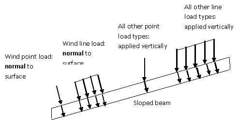
All loads are assumed to have a vertical direction, except wind loads, which are assumed to be normal to the surface, as shown below. Therefore. for all the load types except for wind loads, the load magnitudes are multiplied by the cosine of the slope angle during beam analysis in order to apply only the normal component of the load to the calculation of design stresses.
.

If you wish to enter a wind load that is directed vertically, as from a overturning hold-down device, to a sloped member, then the load magnitude should be multiplied by the cosine of the slope angle. However this situation is quite rare on a sloped beam or joist, which typically supports a roof.
Load intensity adjustment
A further adjustment is necessary for line loads only, due to the assumptions made about the projection of the spans and the load intensity. Dead and wind line loads are assumed along the surface of the member as shown below, and all other line load types are assumed to be applied along the horizontal projection. The beam analysis engine adjusts the load magnitudes of all but the dead and wind loads by multiplying by the cosine of the slope to account for the difference in load extent on a sloped beam as compared to a level beam.
.

.
In summary:
Wind loads
These are assumed to be directed normal to the beam and also have their intensity applied along the slope, so no adjustment is necessary to the input load; analysis proceeds as it would if the beam were level
Dead loads
These are directed vertically but applied along the slope, so one adjustment by the cosine of the slope angle is made.
Live ,snow (and earthquake for Canada) loads
These are assumed to be directed vertically and also applied to the horizontal projection of the member, so two adjustments are made(cosine of slope angle squared).
Refer to Adjustment to Reactions to for the calculations made to re-adjust the reactions that result from these loading assumptions so that they are oriented in a vertical direction and capture the entire vertical component of the applied loads.