Considering two adjacent levels with total story shear of FU above and FL below, the force to be distributed to shear lines on the lower level is F = FU + FL which is used to create the direct component of the lower level shear line forces Fdi . The torsional component of the forces Fti depends on the torsion T in the lower diaphragm, which is affected by the torsions and/or forces transmitted by the shear lines from the upper to the lower level.
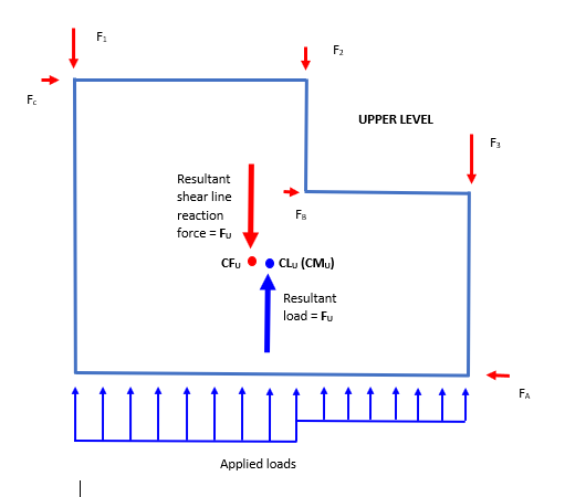
A free body diagram of the upper level diaphragm is shown below. The forces on the upper diaphragm are

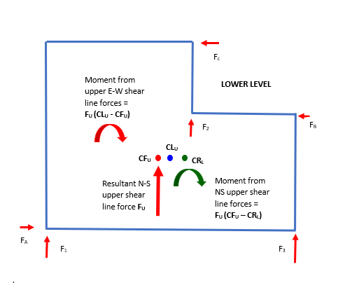
The effect of the shear line forces transferred to the lower level is shown below, where CRL is the center of rigidity on the lower level.

Adding the torsional moments shown, the component Tu coming from the upper level of the torsion TL on the lower level is
TU = Fu (CFU – CRL) + FU ( CLU - CFU) .
= Fu (CLU – CRL)
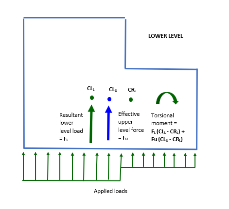
So the model can be simplified by applying the force FU from the upper level, situated at the center of loading of the upper level (center of mass in seismic design), to the lower level, Thus all the forces acting on the level below can be represented as shown below, in which it is assumed for clarity that there is heavier loading on the left hand side of the lower level than the upper (i.e. due to heavier seismic mass or greater area exposed to wind).

The torsional moment TL on the lower level is therefore
TL = Fu (CLU – CRL) + FL (CLL- - CRL)
Defining F = FU + FL and CLF as the centroid of the combined upper and lower level force F,
TL = FU CLU + FL CLL + (FU + FL ) CRL
= (FU + FL ) [ (FU CLU + FL CLL ) / (FU + FL) - CRL ]
= F ( CLF + CRL )
So Shearwalls considers the upper level force as a point load at its center of force, and includes it in the torsional analysis of loads on the level below.
Refer to Transfer of Accidental Eccentricity for a continuation of this development that includes accidental eccentricity.