![]()
![]()
![]()
![]()
|
|
|
|
|
The amount that the wall bottom plate crushes due to the combined overturning and dead force in the end chord studs contributes to the rotational deflection of the wall segment. Shearwalls implements the calculation for this crushing described in SDPWS Example C4.3.4-2.
The expression for deformation ΔC in the bottom plate under the compression-end end post, otherwise known as "crushing", is parameterized by the ratio rf = fc⊥/ Fc⊥'⊥ where fc⊥ is the compressive stress perpendicular to the grain and Fc⊥ is the specified resistance perpendicular compression resistance. There are three intervals in the relation between rf = fc⊥/ Fc⊥' and bottom plate deformation:
Factored vs. Unfactored Resistance
The SDPWS does not address whether the resistance Fc⊥' is factored for moisture and other conditions. However if failure is defined as the force at which there is 0.04" deflection, and factors are applied to that failure strength for member design, the wood must deform more at lower stress levels if subject to moisture, etc.
Therefore, the factored resistance is used:
Fc⊥’ = CM Ct Cb Fc
where
The bearing area factor is applied only to those force locations that are under openings and the opening does not extend to the bottom of the wall. Otherwise it is at the end of the member where the bearing area factor does not apply.
Refer to Design for Compression Forces for more details about these factors.
Load Combinations and Design Methodology
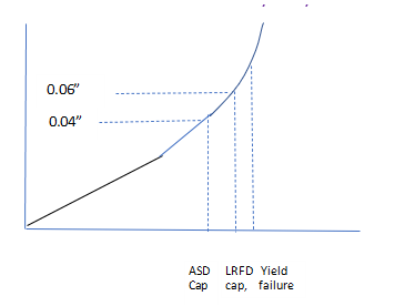
The SDPWS example is for seismic design but uses ASD resistance values to compute deflections for forces calculated with strength (LRFD) load combinations. This is related to how ASD vs LRFD applies safety factors differently to loads vs. capacity – LRFD resistance has a smaller factor; LRFD loads a greater factor.
Because of this, the deflection can go into the cubic range using strength load combinations for deflection, before the perpendicular to grain resistance fails for ASD design. This is shown in the image below: