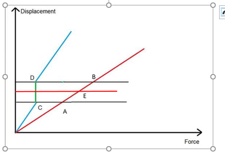
The guarantee of convergence depends on the assumption of continuity in the deflection curve. A discontinuity occurs where the overturning hold-down force becomes just enough to overcome dead load counteracting resistance, a hold-down becomes required, and the deflection jumps by an amount equal to the constant component of hold-down force. For simplicity this is shown for the linear system for two shear wall segments in blue and dark red, below. The horizontal red line represents the common deflection when the deflections on the segments are the same.
.
Point C reflects the deflection when the dead load hold-down component exactly balances overturning and uplift forces, below which no device is required. Values above point D represent deflections when there is a hold-down device. FC = FD is the blue segment force at these points, and there is a range of possible deflection values between these points. The solution on the other segment, FE = V - FC is within the deflection discontinuity. The numerical procedure oscillates between solutions above point D and those below point C, never arriving at the precise force FC at the equilibrium point.
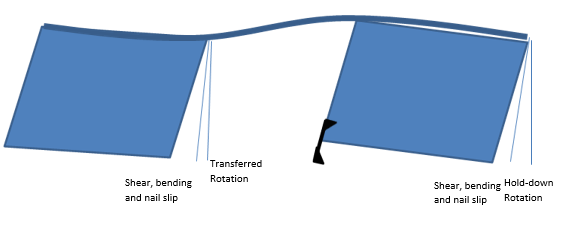
The situation is shown physically, below.

The right segment deflects in shear, bending and nail slip and rotates according to the calculated hold-down displacement. The left segment has no hold-down device, as the dead load exactly balances the overturning force. It also experiences shear, bending and nail slip deflection.
We can assume the end of the left segment is as free to rotate at least as much as the constant component of a hold-down device. The somewhat exaggerated top plate drags the left segment over to equalize total deflection. The amount of transferred hold-down rotation is less than or equal to the effect of the constant component of hold-down displacement.
This illustrates that a unique solution exists, it is just difficult to find. The engineers at WoodWorks are working on a solution to this problem and hope to include it in an upcoming release.