![]()
![]()
![]()
![]()
|
|
|
|
|
The three-term deflection equation combines the shear and nail slip terms
![]()
into
![]()
where the effective shear stiffness Ga is published in the SDPWS shear capacity Tables 4.3A and 4.3B for seismic design only. The formula for Ga for seismic design is given in C4.2.3-3 as
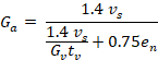
where vs is the seismic shear wall capacity. Shearwalls calculates Ga using the formula rather than using the table. In most cases, the value of Ga is the same as that listed in Table 4.2A, but it may be slightly different because the use of the equation allows us to consider the number of plywood plies when evaluating Gvtv, whereas note 3 of Table 4.2B approximates this effect by applying a factor of 1.2.
MWFRS Wind Deflections
The factor 1.4 appearing in the seismic formula for Ga converts ASD-level shear wall design forces to strength-level deflections (refer to Shear v, Height h, and Length b for details). For main wind force resisting system deflections that are used to distribute forces to segments within a shear line, ASD-level forces are used, so the 1.4 factor is unnecessary. The formula for Ga is just
![]()
For wood structural panels and fiberboard, this results in the same Ga values as for seismic design because the shear wall capacity vw = 1.4 vs. It is important to note that this is merely a coincidence; the difference in capacity for wind vs. seismic is for unrelated reasons pertaining to a historical increase in design wind loads related to test strengths. The increase was not applied to other materials such as gypsum wallboard, and these have different Ga values for wind vs. seismic design.
Serviceability Wind Deflections
For serviceability wind deflections for story drift calculations, the 1.4 seismic factor is replaced by a factor α defined in Wind Story Drift Shear Line Forces that accounts for the effect of using serviceability wind speeds to generate loads and of the serviceability load combination factor. Thee serviceability v when the shear wall is fully loaded is therefore αvw and the formula for Ga is
![]()
where
α = (VSERV / VMWFRS)2 / 0.6
and V refers to wind speed.
Fiberboard and Gypsum Wallboard
Fiberboard and gypsum wallboard, the nail slippage in the 4-term equation is constant, and the 4-term equation is not in fact non-linear. The effect of Ga in the 3-term equation is to vary the shear component deflection from 0 to the deflection at shear wall capacity, rather starting at the constant shear nail slip value. For this reason we were advised by AWC to use the published Ga values, i.e those used for seismic design, for these materials even for wind design.
Unblocked Factor
The unblocked factor Cub is applied only to the v value in the main deflection equation. not the vs and vw values in the calculation of Ga. This is consistent with SDPWS Eqn. C4.3.4.3-2, where it is shown that dividing v by Cub is equivalent to factoring the whole shear stiffness Ga by Cub.
Capacity Increase for 3/8" and 7/16" Sheathing on Unblocked Shear Walls
As per Commentary C4.3.4.3, the capacity Increase for 3/8" and 7/16" sheathing under certain framing conditions from Table 4.2A Note 2, is not applied to vs or vw for unblocked shear walls for the purpose calculating Ga.