The overturning moment due to wall height at the gable end of a structure can be determined in two ways:
Wall Height at Gable Ends - Ceiling Diaphragm
In the Structure input view, for each block, you can specify that the upper level ceiling for that block acts as a diaphragm so that the moment is the height of the wall to the low point of the eave. Note that this approach assumes all roof loads are transferred to the ceiling and then to the walls at the gable ends, which may not be a realistic assumption.
Wall Height at Gable Ends - Roof Diaphragm
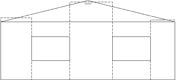
The wall height at gable ends used for the moment arm h in the hold-down force calculation v x h is the average of the heights at the two ends of the shear wall segment, a shown below. If the segment is partially under the gable and partially not, the average height over the whole extent is calculated.

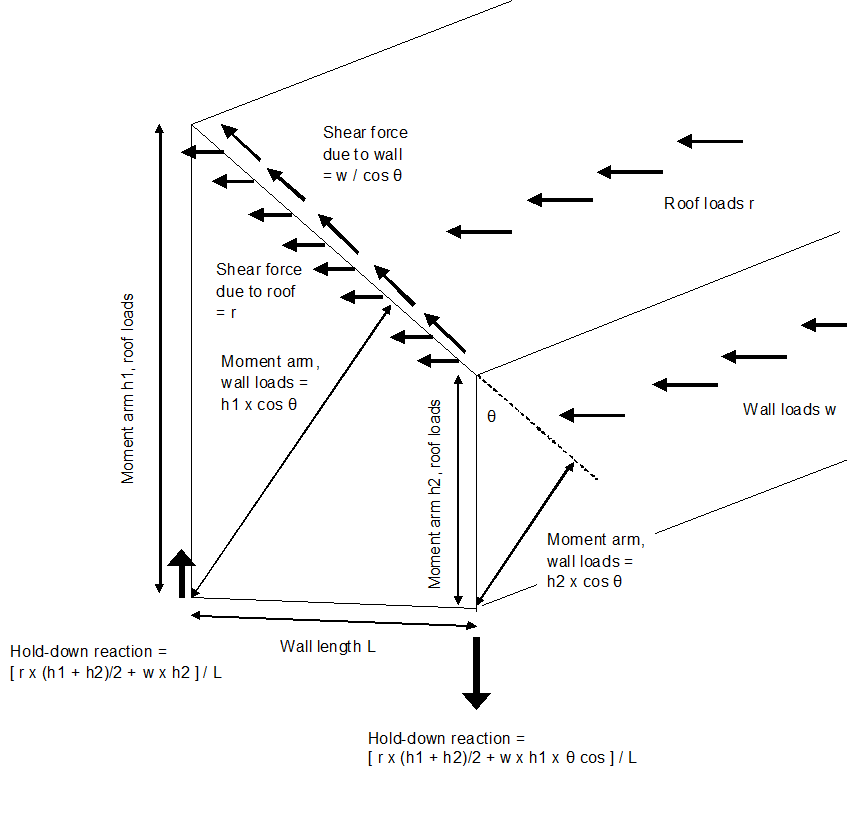
For forces such as the horizontal component of wind loads on the roof panel, or for the horizontal action of the seismic weight of the roof itself, this creates statically balanced forces on the shear line.
For loads that come from the perpendicular wall attached to the roof diaphragm that transmits force to the shear line, either through wind or seismic mass, a more accurate calculation would consider that the shear force is directed along the slope due to the pinned connection between wall and roof rafters. Therefore, you would use an angled moment arm from the base of the wall end to the sloping roof, and a higher force at the top of the shear line. This situation is pictured below. Shearwalls does not consider this complication and uses the average height as the moment arm and the horizontal shear force on the segment, for all loads.
