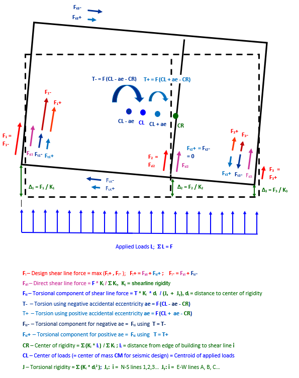
This method accounts for the distribution of shear forces due to the relative stiffness of shear walls and the torsional behavior of a rigid floor diaphragm. The entire floor or roof area is assumed to rotate as a unit due to the moment created by the distance between the center of applied loads (center of mass for seismic design), and the center of shear line rigidity.
Shear line deflections are defined by the fixed boundary of the translated and rotated upper diaphragm at the top of the walls relative to the diaphragm at the bottom. Shear lines are initially apportioned force according to their relative rigidity, and torsional forces added to some shear lines and subtracted from others to account for these deflections.
The situation is illustrated graphically below.

Refer to Torsional Analysis Calculations for the mathematical procedure used.
All the intermediate results of these calculations are presented in the Torsional Analysis Details output file.
Relative Rigidity K
The calculation of the center of rigidity of the diaphragm CR, the direct shear line forces Fdi, the torsional shear line forces Fti, and the overall torsional rigidity J, are all based on the relative rigidities (K) of the shear walls. In the design settings, you can choose to use shear wall capacity to estimate rigidity, or calculate rigidity using deflection analysis.
The recommended method is to use deflection analysis, which calculates rigidity using the deflection-based stiffness of the walls. However, this method is more costly in terms of Design Processing Time.
It is also an acceptable procedure to estimate the rigidity of each wall as the product of the length times its shear capacity. This method does not take into account the effect of the geometry of full height panels on their stiffness.
Torsional Eccentricity
Torsional eccentricity is related to the distance between the centroid of the applied design loads and the center of rigidity of the set of shear walls resisting the loads. The inherent eccentricity is the difference between the center of rigidity and the center of loading CL - CR. For seismic design, the center of loading is the same as the center of mass, and is usually referred to as such.
For some wind and seismic design provisions, to this distance is added and subtracted an accidental eccentricity (ae) to account for uncertainties and variations in distribution of loads or masses and in stiffness. The accidental eccentricity is based on a proportion of building width.
Design Shear Line Force
When there is a requirement of accidental eccentricity, this process creates two torsional forces on each line, one for positive and one for negative accidental eccentricity, which are shown as Fi+ and Fi-. Of the reduced and enlarged eccentricities, the torsional moment considered for each wall is that which causes the largest total shear force when the torsional shear line force is combined with the direct shear line force. So the forces that you see in Plan View and Elevation View are not from a particular accidental eccentricity load case; they represent the worst-case loading, and the sum of the shear line forces exceeds the total applied load. The force transmitted to the level below, however, is equal only to the applied load from the level above.