![]()
![]()
![]()
![]()
|
|
|
|
|
For combined axial and bending design, the program uses the formula from NDS Commentary C15.4-5, rather than equations 15.4-1 to 15.4-4 that are used for other materials. This formula is also given in CLT Handbook, Chapter 8, Section 4.1.4.1, Equation 18, in which the following combined ratio must be less than 1.0:
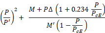
where,
P is the axial load in lbs
P’ is the axial resistance = Fc’ Aeff
M is the maximum moment
Δ is the maximum out-of-plane deflection, including load eccentricity
PcE is the buckling resistance given in NDS C3.7.1-4 - Alternative Buckling Resistance for CLT Wall Panels
Continuously Supported Panels
For the unusual case that the CLT panel would be continuously supported, as described in the NDS C3.7.1-4 topic, the equations lead to a finite value of PcE thus buckling amplification of the secondary moment. However, the derivation of Euler buckling factor involves some simplifying assumptions that break down at very small unsupported lengths, so that this result is unrealistic. For continuously supported members, we assume that there is no amplification due to buckling and this formula is just
![]()